C.R. Laurence/U.S. Aluminum Centerglaze Storefront 1"
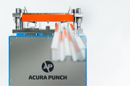
STOREFRONT EXTRUSION PUNCH PRESS
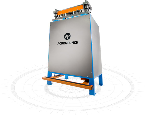
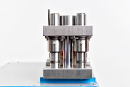
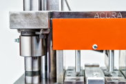
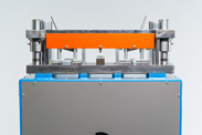
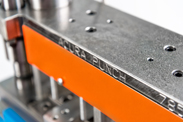
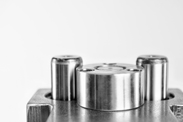
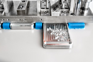
The Acura Punch 3 station die powerfully punches 4 screw holes for 1" and 1/4" CRL/US Aluminum storefront systems and a center station for countersink screw holes allowing you to punch through your extrusions faster up to 10x faster! The punch press system includes: the die system, a highly durable hydraulic unit to power your needs. Compatible with, 450SF, 451SF, IT451
Compatible with C.R. Laurence/U.S. Aluminum Centerglaze Storefront 1/4", C.R. Laurence/U.S. Aluminum Centerglaze Storefront 1"
Improved Efficiency
Compatible with over 85 extrusion systems
10x Faster
HYDRAULIC UNIT |
|
Weight |
340 lb. |
Size |
52" x 42" x 35" |
120V Single-Phase Hydraulic Unit |
|
20 amps |
|
1,000 psi |
|
1 gal hydraulic reservoir |
|
DIE UNIT |
|
Weight |
120 lb. |
Size |
9" x 24" x 10" |
Compatibility |
C.R. Laurence/U.S. Aluminum Centerglaze Storefront 1/4" C.R. Laurence/U.S. Aluminum Centerglaze Storefront 1" |
DIE PLATES |
|
Weight |
6 lb. |
4140 Alloy Steel |
|
Includes M2 Steel Punch Pins |
|
MEASURING SYSTEM |
|
Weight |
40 lb. |
Size |
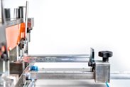
4" x 4" x 146" |
MEASURING SYSTEM STOPS |
|
Size |
2" x 2.5" x 3" |
Features a steel flip-stop |
|
"Acura Punch is the only place we call because they produce what we need, the way we want it."
Wanda Cecil, Kentucky Mirror & Plate Glass, Owensboro, KY
"The Acura Punch is invaluable for screw spline construction. It saves a lot of time. Now, we can punch a piece of storefront in 20-30 seconds that used to take us 10 minutes to do by hand."
Mick Baier, Advanced Glass and Mirror, Lawrence, KS
Troubleshooting
The die set is stuck in the closed position after punching.
How do I correct this?
A) The power to energize the “open” coil on the solenoid valve is not making it to the coil.
Before removing any covers check that the switches the foot pedal depresses when the pedal is released are both being fully depressed. The most common cause of this is the pedal stop bolts that limit the pedals up travel have become out of adjustment. These are located on the front of the machine directly above the pedal. To re-adjust, loosen the locknuts on the stop bolts and screw the bolts In until the switches are limiting the up travel of the foot pedal. Turn the unit on and see if the die will now open. If the die opens properly this was the problem. Bring the stop bolts back down until they touch the pedal and unscrew another ½ turn and use the lock nuts to secure the bolts. Recheck machine operation. These stop bolts take the abuse when the pedal is released and prevent the switches from mechanically bottoming out. Correct adjustment will lengthen the lifespan of the switches.
B) One of the 3 switches is faulty. Check the indicator lights on the solenoid to see if it is receiving power. Only one light should be active at a time. If it is not then have an electrician check the switches or replace the switches and confirm all wire connections are tight.
C) Faulty coil or stuck solenoid valve. With the unit running manually shift the solenoid spool back and forth. If the spool is free and the unit still won’t operate the coil on the solenoid is faulty.
Read MoreWhen I punch the metal it is leaving a burr. What is causing this?
The proper punching of holes is highly dependent of the clearances between the punch pin and the die plate hole and the sharpness of both. If the die plate hole has become oval shaped these clearances are affected. Once the clearance becomes too large the metal will be pushed forming a raised burr on the bottom instead of a clean shear. The die plates and punches will need replaced. To get the longest life of the consumable parts make sure to fully close the die when punching and never try to re-punch holes to elongate them or to confirm they were punched through.
Changing the Die, Punches and Plates
How often should I change the punches and plates?
When the quality of the hole becomes unacceptable due to burrs or the punch pin have excessive aluminum buildup causing the extrusion to be damaged when being stripped from the punch pins.
Can I change the punches and plates myself?
Yes. It is recommended to mark the front of the die plates and punch holder before removal to aid in the indexing of the parts during reinstallation.
How do I change the die?
1. Press the hydraulic unit foot pedal until the die closes.
2. Shut off the hydraulic unit while pressing down on the foot pedal.
3. Remove (6) 5/16" bolts on the cylinder rod nuts (3 per nut).
4. Turn the hydraulic unit on for 2 seconds to release pressure on the nuts.
5. Next, unplug the hydraulic unit.
6. Remove (2) cylinder rod nuts.
7. Remove the (4) 1/2" bolts the die to the hydraulic unit.
8. Lift the die from the hydraulic unit utilizing the appropriate lifting device.
9. Place the new die on the hydraulic unit.
(Note: While placing the die on the unit, make sure the
1/2" steel rod on the right side of the hydraulic unit (in front of the cylinder rod is aligned with the hole in the die base. If the rod is depressed more than 2.5" it will stretch and the rod return springs.)
-----WARNING: KEEP FINGERS CLEAR OF THE AREA BETWEEN THE DIE AND HYDRAULIC UNIT----
10. Install the (4) 1/2" bolts holding the die to the hydraulic unit.
11. Install (2) cylinder rod nuts so that the top of the nuts are flush with the top of the cylinder rods.
12. Plug in the hydraulic unit.
13. Turn on the hydraulic unit.
14. Depress the foot pedal until both nuts contact the top of the die firmly.
15. Turn off the unit while pressing down on the foot pedal.
16. Release the foot pedal and turn the hydraulic unit on and then back off quickly.
(Note: This should raise the nuts off the top of the die approx 1/8".)
17. Rotate the nuts either direction to align the (6) bolt holes.
18. Thread the (6) 5/16" bolts into the top 4-5 turns.
19. Depress the foot pedal and turn the hydraulic unit back on.
-----CAUTION: CYLINDER ROD NUTS WILL BE MOVING DOWN WHEN THE SWITCH IS TURNED ON----
20. When the nuts contact the top of the die top, firmly turn the hydraulic unit off while holding the foot pedal down.
21. Tighten the (6) 5/16" bolts.
22. Lastly, apply a liberal coat of rust preventer (ex. WD-40) to the die that is going to be stored.
HYDRAULICS
What are the electrical requirements of the hydraulic unit?
The hydraulic unit operates on single phase 120VAC single phase requiring 20 amps. A dedicated 30 amp circuit is recommended.
How full should the hydraulic reservoir be?
The oil level should be .5” to 2” from the top of the reservoir.
What type of oil does the hydraulic unit take?
Mobile DTE24 or equivalent.
How often should I grease the die set?
The guide post bushings should be greased weekly or every 10 hours of operation.
How can I adjust the pressure of the hydraulic unit?
Yes, the hydraulic pump does have a pressure adjustment. It is located on the back of the pump body.
DIE SET HANDLING
How do I adjust the open height of the die?
The open height of the die is adjustable by moving the bar that is attached to the ½” diameter return rod. Lowering the bar will increase the open height and vice versa.
Should I spray the punch pins with oil?
Light oil sprayed on the pins frequently will help to keep the aluminum build up to a minimum which will help with the stripping of the metal off of the pins after punching however there is no dramatic effect on the life of the parts wet of dry.
ORDERS
How can I check my order status?
You can check your order status online at http://acurapunch.com/Orders/SignIn or call 785-456-2684.
|
Replacement Pins and Punch Plates 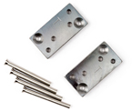
Compatible with C.R. Laurence/U.S. Aluminum Centerglaze Storefront 1" ADD TO CART |
Other Compatible Replacement Pins and Punch Plates 
Compatible with C.R. Laurence/U.S. Aluminum Centerglaze Storefront 1/4" ADD TO CART |
Punch Press Stand / Hydraulic Unit  The double cylinder hydraulic machine is the foundation for the entire punch press system. The hydraulic unit comes complete with a 120 volt, 1 phase 2 Horse Power Motor that is Compatible with any Acura Punch die set available. ADD TO CART |
Hydraulic Cylinder  Replacement hydraulic cylinder. Compatible with all Acura Punch hydraulic stands. ADD TO CART |
|
Hydraulic Cylinder Seal Kit  Replacement seal kit needed to rebuild one hydraulic stand cylinder. ADD TO CART |
Hydraulic Reservoir 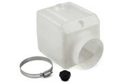 Replacement hydraulic oil tank for 2 horsepower motor. (Filter screen, Return tube, Suction tube, Hose clamp and O-ring). ADD TO CART |
2X894 Switch 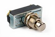 Replacement foot pedal limit switch located on the bottom left. Normally open microswitch. ADD TO CART |
2X901 Switch 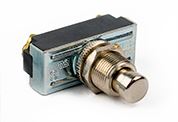 Replacement foot pedal limit switch located bottom right and top return rod. Normally closed microswitch. ADD TO CART |
|
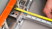
12’ Measuring System 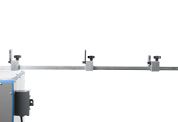 Includes measuring bar, support leg, tape measure, and 3 stops. ADD TO CART |
Measuring System Stop 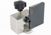 Each stop is built to be adjusted along the measuring system bar. ADD TO CART |
Measuring Tape 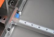 Flexible 12 ft. measuring tape compatible with the 12' measuring bar. ADD TO CART |
1” Lexan Guides 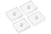 Protects aluminum extrusions from scratches while punching. Set of 4. ADD TO CART |
|
¼” Lexan Guides 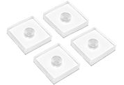 Protects aluminum extrusions from scratches while punching. Set of 4. ADD TO CART |

